|
Operation & Structure
A best stepper motor from china rotates with a fixed step angle, just like the second hand of a clock. Highly accurate positioning can be performed with open-loop control thanks to the mechanical structure within the motor. Accurate Positioning (Number of Steps) While having full control of rotation and speed, the simple structure of stepper motors is achieved without using electrical components, such as an encoder within the motor. For this reason, stepper motors are very robust and have high reliability with very few failures. As for stopping accuracy, ±0.05° (without cumulative pitch errors) is very accurate. Because positioning of stepper motors is performed by open-loop control and operated by the magnetized stator and magnetic rotor with small teeth, stepper motors have a higher follow-up mechanism toward commands than that of servo motors. Also, no hunting occurs when stopping stepper motors. They are also excellent in belt drives, which have low rigidity. Useful for Speed Control and Position Control When pulses are input to a driver through a pulse generator, stepper motors position according to the number of input pulses. The basic step angle of 5-phase stepper motors is 0.72° and 1.8° for 2-phase stepper motors. The rotating speed of the stepper motor is determined by the speed of the pulse frequency (Hz) given to the digital stepper motor driver, and it is possible to freely change the motor rotation by simply changing the number of input pulses or frequencies to the driver. Stepper motors not only serve as position control motors, but also as speed control motors with high synchronization. Stepper Motors Uses: • High frequency, repetitive positioning of fixed step angles • Positioning that requires long stopping time due to width adjustment, etc. • Fluctuating loads and changing rigidity • Positioning that divides 1 cycle • Motor shafts that requires synchronous operation
0 Comments
When using a CNC stepper motor, integrating an incremental encoder is relatively straightforward. Still, there are some general guidelines to consider.
Incremental stepper motor encoders (like any encoder) all function as part of a feedback system — providing closed-loop operation. Using information from the encoder, the drive system alters motor operation. Keep this in mind when using and driving a stepper motor, because the machine design must set to a reference position when using incremental encoders. Incremental encoders are often useful when speed control requirements are part of a system. If there’s less concern over the position of the shaft — and more of a concern over how fast it is moving — then the fact that incremental encoders don’t track position once off is less critical. In fact, here their simple operation and low price benefit the design. Incremental encoders keep track of speed where only the difference between two positions is necessary. There are a few different methods to mount an encoder to a stepper motor. Each of them is useful for various situations, and the choice depends on the motion system. Incremental encoders with shaft mounting A coupling connects the encoder to the shaft. This creates mechanical and electrical isolation, but also adds cost because the coupling is an extra part and because this method requires a longer motor shaft. Incremental encoders with a hub or hollow-shaft setup The encoder directly mounts to the motor using a spring-loaded tether. This is a design that is easy to install and requires no alignment. The only caveat is that this geometry requires careful electrical isolation. Incremental encoders with a bearingless or ring mount Here, the sensor is in the form of a ring that mounts to the motor’s surface. A wheel mounts to the motor’s shaft. There are useful for heavy-duty applications. How Feedback Encoder of Step Motor Operate 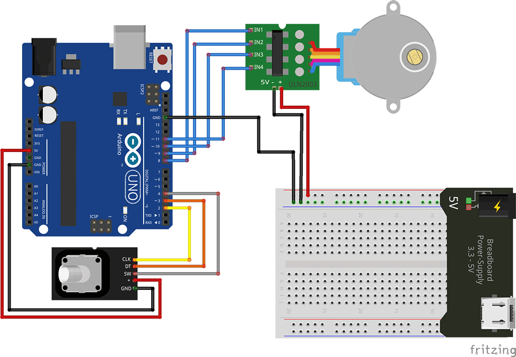 I'm really bad with this coding part of using two stepper motor encoder encoders to control two stepper motors [using 28BYJ-48 stepper motor with the ULN2003 board]. This code works fine using one rotary encoder for one stepper motor using this off oyostepper.com.
When I slightly modify the code for two encoders and two stepper motors I'm using this: However I'm not getting the results I expected. The two motors just don't respond. #include "Stepper.h" #define STEPS 32 // Number of steps for one revolution of Internal shaft // 2048 steps for one revolution of External shaft volatile boolean TurnDetected; // need volatile for Interrupts volatile boolean rotationdirection; // CW or CCW rotation const int PinCLK = 2; // Generating interrupts using CLK signal const int PinDT = 3; // Reading DT signal const int PinSW = 4; // Reading Push Button switch const int PinCLK2 = 46; const int PinDT2 = 47; const int PinSW2 = 48; int RotaryPosition = 0; // To store Stepper Motor Position int RotaryPosition2 = 0; int PrevPosition; // Previous Rotary position Value to check accuracy int PrevPosition2; int StepsToTake; // How much to move Stepper int StepsToTake2; // Setup of proper sequencing for Motor Driver Pins // In1, In2, In3, In4 in the sequence 1-3-2-4 Stepper small_stepper(STEPS, 8, 10, 9, 11); Stepper small_stepper2(STEPS, 40, 41, 42, 43); // Interrupt routine runs if CLK goes from HIGH to LOW void isr () { delay(4); // delay for Debouncing if (digitalRead(PinCLK)) rotationdirection = digitalRead(PinDT); else rotationdirection = !digitalRead(PinDT); TurnDetected = true; /////I added this delay(4); // delay for Debouncing if (digitalRead(PinCLK2)) rotationdirection = digitalRead(PinDT2); else rotationdirection = !digitalRead(PinDT2); TurnDetected = true; } /////up to here void setup () { pinMode(PinCLK, INPUT); pinMode(PinDT, INPUT); pinMode(PinSW, INPUT); digitalWrite(PinSW, HIGH); // Pull-Up resistor for switch attachInterrupt (0, isr, FALLING); // interrupt 0 always connected to pin 2 on Arduino UNO pinMode(PinCLK2, INPUT); pinMode(PinDT2, INPUT); pinMode(PinSW2, INPUT); digitalWrite(PinSW2, HIGH); // Pull-Up resistor for switch attachInterrupt (0, isr, FALLING); // interrupt 0 always connected to pin 2 on Arduino UNO } void loop () { small_stepper.setSpeed(600); //Max seems to be 700 if (!(digitalRead(PinSW))) { // check if button is pressed if (RotaryPosition == 0) { // check if button was already pressed } else { small_stepper.step(-(RotaryPosition * 50)); RotaryPosition = 0; // Reset position to ZERO } } // Runs if rotation was detected if (TurnDetected) { PrevPosition = RotaryPosition; // Save previous position in variable if (rotationdirection) { RotaryPosition = RotaryPosition - 1; } // decrase Position by 1 else { RotaryPosition = RotaryPosition + 1; } // increase Position by 1 TurnDetected = false; // do NOT repeat IF loop until new rotation detected // Which direction to move Stepper motor if ((PrevPosition + 1) == RotaryPosition) { // Move motor CW StepsToTake = 50; small_stepper.step(StepsToTake); } if ((RotaryPosition + 1) == PrevPosition) { // Move motor CCW StepsToTake = -50; small_stepper.step(StepsToTake); small_stepper2.setSpeed(600); //Max seems to be 700 if (!(digitalRead(PinSW2))) { // check if button is pressed if (RotaryPosition2 == 0) { // check if button was already pressed } else { small_stepper2.step(-(RotaryPosition * 50)); RotaryPosition2 = 0; // Reset position to ZERO } } // Runs if rotation was detected if (TurnDetected) { PrevPosition2 = RotaryPosition2; // Save previous position in variable if (rotationdirection) { RotaryPosition2 = RotaryPosition2 - 1; } // decrase Position by 1 else { RotaryPosition2 = RotaryPosition2 + 1; } // increase Position by 1 TurnDetected = false; // do NOT repeat IF loop until new rotation detected // Which direction to move Stepper motor if ((PrevPosition2 + 1) == RotaryPosition2) { // Move motor CW StepsToTake = 50; small_stepper2.step(StepsToTake); } if ((RotaryPosition2 + 1) == PrevPosition2) { // Move motor CCW StepsToTake = -50; small_stepper2.step(StepsToTake); } } } } } http://forum.cncprovn.com/threads/3967-CKD-Suu-tam-Arduino-closed-loop-Stepper-motor?p=151859 https://forum.level1techs.com/t/closed-loop-control-for-3d-printers/80674/3 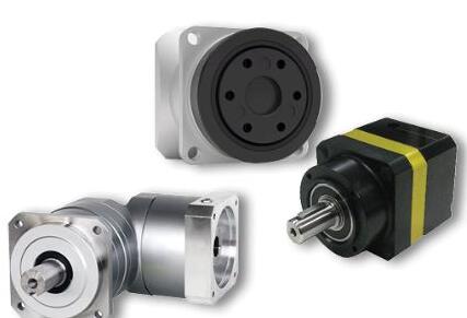 Gearing stepper motor (components or housed gearboxes) are mechanical devices used to increase the output torque or change the speed (RPM) of a motor. They are also used for inertia matching between a load and a motor. The most common type of gearing product is a gearbox (or housed gearhead).
Most gearboxes are constructed from steel materials such as iron, aluminum and brass, however spur gearboxes can also be made with plastics such as polycarbonate or nylon. The orientation of the gear teeth plays a major role in the overall efficiency, torque and speed of the system. Straight gear teeth gearboxes are typically used in low-speed applications. These gearboxes can be noisy, and usually have lower overall efficiency. Helical gearboxes are typically used in high-speed applications. These gearboxes are quieter in operation than straight gear teeth gearboxes and usually have improved overall efficiency. In very low noise applications, ceramic gears can be used to replace metal gears. Gearboxes come in a variety of types: Planetary, Strain Wave Gearing, Bevel, Helical, Spur, Cycloidal, etc. Search our Gearing Products by supplier: geared nema 17 stepper motor geared stepper motor nema 23 I have a stepper motor but do not have the pinouts for the motor. How can I determine how to wire my best stepper motor without the pinouts?
Solution In general, 2-phase stepper motors can have 4, 6 or 8-wire leads (not including any optional encoder lines). Some stepper motors have a motor case ground that can be tied to the ground of the system. It is usually a black wire, and it will add one additional wire to the overall count (4 coil wires + 1 casing ground = 5 wires total). The best solution is to obtain the pinout from the motor manufacturer. If you do not have access to the pinout, then the following procedure will help you in wiring the 2-phases. If you have four coil wires from the stepper motor: Approach 1 (using a multimeter) Each of the two phases should have the same resistance when measured with a multimeter. When measuring the resistance across one wire from each of the two phases, the resistance should be infinite because the circuit is open. Locate the two pairs of wires that represent the two phases; both pairs of wires will have similar internal resistance. Connect each phase to the amplifier and ignore the polarity (+ / -), for now. You have a 50 percent chance of guessing right. Send a command to move the motor. If the motor rotates in the wrong direction, then switch either phase A and A- or B and B- (effectively reversing directions). Approach 2 (without a multimeter) Connect the four coil wires to the amplifier in any arbitrary pattern. Send a command to move the motor. If the motor moves erratically or not at all, then switch one wire from phase A with one wire from phase B. If the motor is rotating in the wrong direction, then switch either phase A and A- or B and B- (effectively reversing directions). If you have six coil wires, then each phase has a center tap wire: The center tap wire should have half the internal resistance of the full phase. The easiest option is to use a multimeter to find the two pairs of wires that have the maximum resistance. Connect each phase to the amplifier, and ignore the polarity (+ / -) for now. You have a 50 percent chance of guessing right. The motor should rotate, and if it is in the opposite direction, then switch either phase A and A- or B and B- (effectively reversing directions). If you have eight coil wires, then it is highly recommended you find the exact pinout for the motor. The eight wires of stepper motor nema 17 or hybrid stepper motor nema 34 represent four pairs of wires, and each pair has the same resistance. It is not easy to find what two pairs represent phase A and phase B without dismantling the motor. www.wordpress.com/2018/09/13/what-are-the-advantages-and-disadvantages-of-the-different-functionalities/ Some basic questions concerning Stepper motor with geared head/geared box.
What is the meaning the reduction 1:56 (1/56) or 1:100 (1/100) or 18/1? According to some charts: How can i know (calculate) the RPM from the reduction ratio? Why there are more reduction for the same Holding torqoue (eg.: J57HB56-03 Holding torque = 0,9 Nm but the reduction can be 1:3 or 1:5)? Does it have affect on the motor life long if i use great reduction (1:100) to increase the torqoue from smal stepper motor? I mean that motor life wil be shorter. First thing first, nema 23 geared reduction of 1:56 means that for every 56 turns the end shaft of the gear box will do 1 turn. The more gear reduction you have the slower the motor will turn but with higher torque. When using a gearbox you are trading motor speed for torque. It is quite simple calculating the RPM from the reduction ratio. Assuming you motor spins at 500 RPM and your gear is 1:46 then the motor with gear will spin at 500/46 = 10.86RPM. In stepper motors it is not so simple to determine what is the motor top speed as it depends on the voltage you use, the driver (better drivers can drive the motor faster) and the quality of the motor. It is also important to know that stepper motors have different torques in different RPMS and "Usually" (but not always) the slower you go the more torque you have. Gearbox does not affect gear reduction stepper motor life no mater what is the gear ratio. Each gearbox has a torque limit and applying a torque higher than the maximum recommended torque will damage the gearbox. 2 Methods To Design Stepper Motor Control Circuit Top Ten Stepper motor Advantages:
Stable. Can drive a wide range of frictional and inertial loads. Needs no feedback. The stepping motor is also the position transducer. Inexpensive relative to other motion control systems. Standardized frame size and performance. Plug and play. Easy to setup and use. Safe. If anything breaks, the motor stops. Long life. Bearings are the only wear-out mechanism. Excellent low speed torque. Can drive many loads without gearing. Excellent repeatability. Returns to the same location accurately. Overload safe. Motor cannot be damaged by mechanical overload. Top Ten DC Servo motor Advantages: High output power relative to motor size and weight. Encoder determines accuracy and resolution. High efficiency. It can approach 90% at light loads. High torque to inertia ratio. It can rapidly accelerate loads. Has "reserve" power. 2-3 times continuous power for short periods. Has "reserve" torque. 5-10 times rated torque for short periods. Motor stays cool. Current draw proportional to load. Usable high speed torque. Maintains rated torque to 90% of NL RPM Audibly quiet at high speeds. Resonance and vibration free operation. Top Ten Stepper Disadvantages: Low efficiency. Motor draws substantial power regardless of load. Torque drops rapidly with speed (torque is the inverse of speed). Low accuracy. 1:200 at full load, 1:2000 at light loads. Prone to resonances. Requires microstepping to move smoothly. No feedback to indicate missed steps. Low torque to inertia ratio. Cannot accelerate loads very rapidly. Motor gets very hot in high performance configurations. Motor will not "pick up" after momentary overload. Motor is audibly very noisy at moderate to high speeds. Low output power for size and weight. Top Ten DC Servo Disadvantages: Requires "tuning" to stabilize feedback loop. Motor "runs away" when something breaks. Safety circuits are required. Complex. Requires encoder. Brush wear out limits life to 2,000 hrs. Service is then required. Peak torque is limited to a 1% duty cycle. Motor can be damaged by sustained overload. Bewildering choice of motors, stepper motor encoder, and servodrives. Power supply current 10 times average to use peak torque. See (5). Motor develops peak power at higher speeds. Gearing often required. Poor motor cooling. Ventilated motors are easily contaminated. 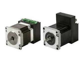 Technological advancements are changing the performance-cost ratio between stepping motors and servo motors for a growing variety of demanding industrial automation applications. Thanks to the adoption of closed-loop technology, less expensive steppers are making inroads into applications that have been considered the exclusive domain of more expensive servos. Steppers vs. servos Conventional wisdom states that servo control systems are superior in applications requiring speeds greater than 800 revolutions per minute (RPM) as well as applications that require high dynamic response. Stepper motors are preferable in applications that run at lower speeds, produce low to medium acceleration rates, and/or require high holding torque. The conventional wisdom, however, doesn't consider other aspects regarding steppers and servo motors. Motor design A stepper motor online rotates in steps and uses magnetic coils to pull a magnet in steps from one position to the next. To move the motor 100 positions in a given direction, the circuit steps the motor 100 times. The stepper moves incrementally using pulses and can be precisely positioned without a feedback sensor. Simplicity and cost Steppers are less expensive than servos and are easier to commission and maintain. Steppers are stable at rest and hold their position, even with dynamic loads. However, as the demands of certain applications increase, more expensive and complex servos must be applied. Positioning A crucial difference between steppers and servos is in applications that require knowledge of the precise position of the machine at every moment. Speed and torque Performance differences between steppers and servos derive from their dissimilar motor designs. Stepper motors have a lot more poles than servo motors, thus one complete rotation of a stepper motor requires many more current exchanges through the windings, causing its torque to fall off dramatically as speed increases. Heat, energy consumption Open-loop stepper motors operate with a constant current and give off a significant amount of heat. Closed-loop control avoids the heat problem by supplying just the current demanded by the velocity loop. Servo control systems are best suited to high-speed applications that involve dynamic load changes like robot arms. Motion control systems that require the properties of servos must justify the higher cost of these motors. Stepper control systems are preferred for applications that require low-to-medium acceleration and high holding torque such as 3-D printers, conveyors, and accessory axes. Because they are less expensive, steppers can lower the cost of automation systems. Closed-loop stepepr motor technology advancements enable stepper motors to step into high-performance, high-speed applications formerly reserved for servos. Courtesy: ServotronixChanging perceptions What if the advantages of closed-loop servo technology could be adapted to steppers? Could the cost benefits of steppers be realized if they achieved servo-like performance? When The Going Gets Tough, The Tough Get Gearmotors 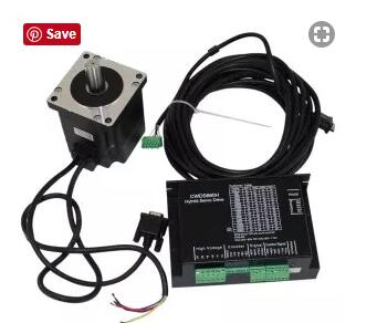 A closed-loop step motor system combines the advantages of servo motor and stepper motor technologies. Functionally, a closed-loop stepper motor system will run much more smoothly and with less resistance than a standard stepper motor setup. Since a closed-loop system provides feedback and control as well as short transient and free oscillation times, the closed-loop system will not lose or gain steps. A closed-loop nema 34 stepper motor system, such as the 86BHH76-860H, may be the best option when the application requires improved energy efficiency and smoothness of operation, especially at high loads. In addition, a closed-loop system has the advantage over servo motor systems of higher torque at low RPMs. Additional benefits include short transient times, less packaging, accurate/correct positioning using feedback from encoders integrated into the motor(s) to the controller, and comparatively low prices. When The Going Gets Tough, The Tough Get Gearmotors 1.1) Introduction of Product The DDCSV1 is the 4 axis and 4 axes motion controller which has been researched and developed by Faster CNC for four years. The control period of each position is only 4 milliseconds, with a high control precision. The highest uniaxial output pulse is 500KHz and the pulse width can be adjusted. It supports the common stepper motor and servo motor. The DDCSV1 numerical control system adopts the ARM+FPGA design framework. The ARM can finish the part of human-computer interface and code analysis and the FPGA can finish the part of underlying algorithm and control pulse generate, with the reasonable design, reliable control and easy operation. 1.2 ) Performance parameter of Product Ordinary digital input interface of 16-circuitoptocoupler coupling isolation Ordinary digital input interface of 3-circuit optocoupler coupling isolation Output interface of 0-10V spindle control port with analog quantity(can be modified as PWM output); Support the 3 axis stepper motor control, the highest control pulse output of single axis is 500KHz; ARM9 main control chip; FPGA core algorithm chip; 4.3 inches TFT screen, resolution ratio: 480*272; 17 operational keys; The main control equipment is 18V-32V power input, the current capacity is required not to be lower than 0.5A; Support the USB flash disk to read the G code,and the size of G codefile has no requirement; Be equipped with MPG port and support digital display MPG as well as support the general MPG in the market Support the panel key with single-axis manual operation, manual step and CONToperation; (cnc stepper motor kit - 3 axis cnc kit) Support the operation of quickly specify the running position; Support the multi coordinate systems (with automatically saving function in case of power cut); Support the function of saving data automatically after power down (press the start to automatically save the data in the operation, automatically save the data after power down) 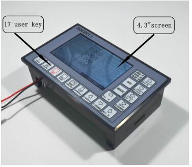 |
 RSS Feed
