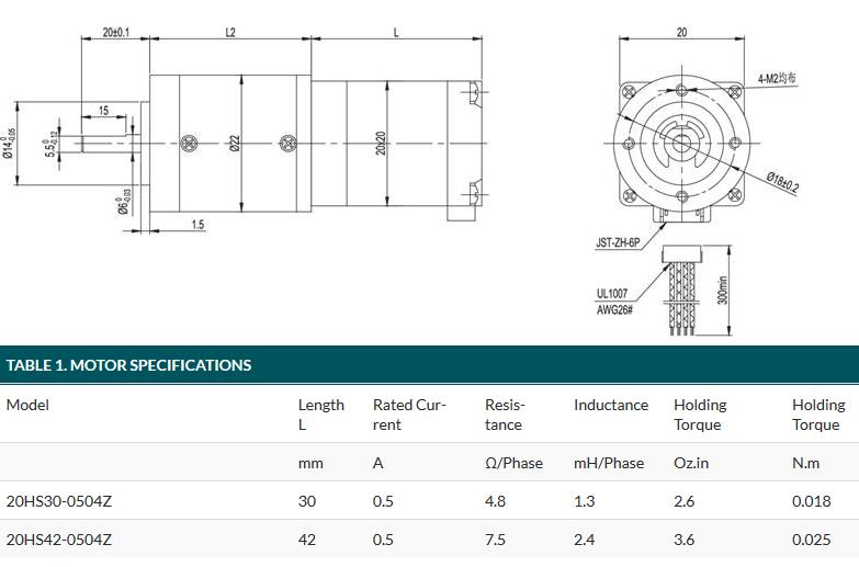
 Geared Stepper Motor Nema 23 High Torque Gear Ratio 15:1 214 kg-cm
Stepper motors are great for position control. They can be found in desktop printers, plotters, 3d printers, CNC milling machines, and anything else requiring precise position control. These are a special segment of brushless motors. They are purposely built for high-holding torque. This high-holding torque gives the user the ability to incrementally “step” to the next position. This results in a simple positioning system that doesn’t require an encoder. This makes stepper motor controllers very simple to build and use. This particular stepper has a Nema 23 frame size MOTOR with Gear Ratio of 15:1, and has a holding torque of 214 kg-cm. Here are a few applications where they are often found: Printers CNC machines 3D printer/prototyping machines (e.g. RepRap) Laser cutters Pick and place machines Linear actuators Hard drives
0 Comments
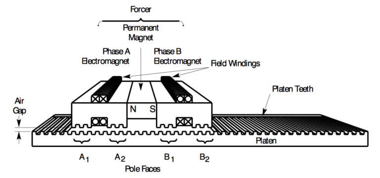 Like most linear motors, a linear step motor is essentially a variation of the rotary design, cut radially and laid out flat. Similar to their rotary counterparts in operation and performance, a linear stepper motor is typically run as open-loop systems and are capable of providing high resolution at high speeds and accelerations. The linear stepper motor almost exclusively employs a hybrid design, with two main parts—a base (also referred to as a platen) and a slider (also referred to as a forcer). Unlike other linear motor designs, in a linear stepper motor, the platen is a passive component—a steel (or stainless steel) plate with slots milled into it. The forcer contains laminations with slotted teeth, motor windings, and a permanent magnet. The teeth of the forcer concentrate the magnetic flux that is created when current is applied to the coils. The forcer teeth are also staggered in relation to the platen teeth—typically by ¼ tooth pitch—to ensure that constant attraction is maintained and that the next set of teeth will come into alignment as current is switched in the coils. For each full step of the motor, the forcer moves ¼ tooth pitch. The magnetic flux between the forcer and the platen creates a very strong magnetic attraction, so bearings—either mechanical roller bearings or air bearings—are typically integrated into the linear motor system to maintain the correct air gap between the forcer and the platen. When air bearings are used, the platen serves as the air bearing surface. Both full step operation and microstepping are possible with precision linear stepper motors, but microstepping is often used in order to minimize resonance, which occurs when the rate of input pulses coincides with the natural oscillation frequency of the motor. Resonance causes a loss of torque and can lead to missed steps and errors in positioning. Microstepping also increases the motor’s resolution, although at the expense of torque. Tips on Choosing the Right DC Gear Motor 4 Simple Steps To Select a Gear Motor 1.Greater operating safety on vertical axes
To prevent uncontrolled downward movement due to gravity in the event of a power failure or emergency stop, Nanotec brakes are primarily used in Z-axes for personal and property protection. 2.Safety brake and holding brake All Nanotec brakes are holding brakes or safety brakes with two frictional surfaces (stepper motor with brake), and the brakes are ventilated or opened by applying a voltage of 24VDC. They are almost always installed on the B-bearing side of electric motors. Braking of motion is effected by the controlled drive, whose rotational speed is first reduced to zero (to a standstill) before the safety brake closes. BKE brakes are electromagnetically ventilated brakes for dry operation whose braking force is generated by permanent magnets. BW and BL brakes are spring-force ventilated brakes whose braking force is generated by a compression spring. When no current is applied, springs push against the anchor disc of the brake. The friction linings of the rotor, which is connected to the motor shaft via toothing, are clamped between this anchor plate and the mounting surface (rear side of motor) of the brake. When current is applied to the brake coil, a magnetic field builds up that pulls in the anchor plate and releases the rotor with the friction linings. The brake is ventilated. The specified torques apply for dry operation with absolutely grease-free frictional surfaces. The torque is lower for greased frictional surfaces. 3.Emergency stop brake The steps required to stop a system safely need to be examined and checked in the form of a risk analysis as part of a disaster management plan or machine safety program. Nanotec brakes meet the static holding torques specified in the data sheet but cannot additionally handle the often considerable dynamic loads that arise when braking a moving load. If the dynamic load is in the range of the static load on the brake (work of friction, rotational speed, kJ, duty cycle, etc.), the brake can be used as an emergency stop brake 10 times before it needs to be inspected and usually replaced. Especially in regions with unstable power supplies, power failures and emergency stops may be quite frequent (causing uncontrolled movements) and machine safety should not be underestimated in these situations. See more:https://www.oyostepper.com/ Stepper Motor Settling Time (Ringing) and Resonance
When the stepper motor receives the final pulse signal, (either one or from a continuous train), it will stop rotating. However, complete rest will not occur until all the oscillations have stopped. The time it takes from the application of the last pulse received until the stepper motor comes to a complete rest is known as settling time. (See graph below). Resonance occurs when the stepper motor suddenly makes large oscillations, or the output torque suddenly drops at one certain pulse rate or numerous small regions of pulse rates. The stepper motor will stop (stall), may miss steps or reverse direction from the commanded direction. This phenomenon occurs when the natural frequency of the stepper motor coincides with the frequency of the input pulse rate. This generally occurs around 100 - 200 pulses per second in a full-step operation, and also at higher pulse rates. Microstepping half-step operation, or electrical or mechanical damping, can reduce resonance issues. Microstepping has a large effect on settling time and resonance due to the smaller angular displacement taken per pulse. See Figure below. Resonance Characteristics Since a stepper motor system is a discreet increment positioning system, it is subject to the effect of resonance. Where the system is operated at this given frequency, it may begin oscillating. The primary resonance frequency occurs at about one revolution per second. Oscillating will cause a loss of effective torque and may result in a loss of synchronism. Settling time and resonance can be best dealt with by dampening the stepper motor's oscillations through mechanical means. Mechanically, a friction or viscous damper may be mounted on the stepper motor to smooth out the desired motion. Methods for Changing or Reducing Resonance Points: Use of Gearboxes or Pulley Ratios Utilize Microstep Drive Techniques Change System Inertia Accelerate Through Resonance Speed Ranges Correct Coupling Compliance Encoders Although stepper motors do not require an stepper motor encoder for sale, Anaheim Automation's double-ended shaft stepper motors are "encoder-ready" as standard construction. Encoders aid in determining whether or not the final position has been achieved. Anaheim Automation indexers contain electronics that allow position correction to be obtained. Although the standard incremental encoder provides 4,000 counts per shaft revolution, this does not limit the step resolution to 4,000. It does mean however, that if an encoder is being used for closed-loop positioning, a "deadband window" would exist. Automated Applications of Stepper Motor Some Questions about NEMA 17 Motor for 3D Printers 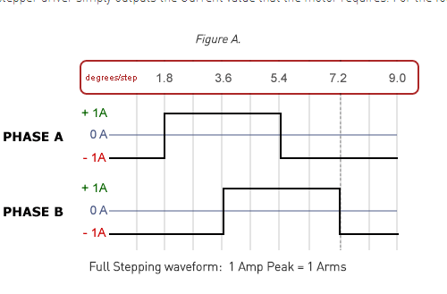 stepper Motor Drivers specify the amount of Current that they output to a stepper motor in either RMS or Peak Current. How are they different?
This tutorial will walk you through the difference between the two types of current used when specifying stepper drives and motors. You will learn about the relationship between RMS and Peak current and why this connection is important when configuring stepper control systems. After exploring the technical merits of RMS vs Peak Current, you'll understand why stepper motor china wholesale manufacturers only specify torque curves and maximum ratings in RMS Current, rather than Peak Current - while also using a stepper driver that is specified in RMS Current. What is the benefit to you? It simplifies the matching of a stepper motor to a stepper driver in any application. The next few paragraphs will shed light on this statement. RMS, which stands for Root Mean Square, is a fundamental measurement of the magnitude of an Alternating Current (AC) signal. The RMS value equals the amount of Direct Current (DC) required to produce an equivalent amount of heat in a same sized load. The shape of the alternating Current AC waveform is not important. RMS values simplify the calculation of average power and energy. However, Peak values, which only give the maximum value of the AC signal, require more information and can only be compared to RMS values if the shape of the waveform is known. For example, when the AC waveform is an ideal sine wave, the relationship between RMS and Peak Current is as follows: RMS Current = Peak Current x 0.707 or Peak Current = RMS Current x 1.414. The relationship between RMS and Peak stepper Current depends on the driver’s configuration. The three common modes of operation for Stepper Motor Drivers include Full-Stepping, Half-Stepping, and Micro-stepping. If you were to view the Current waveform of these three modes on an oscilloscope, they would all appear different representing the relationship between the RMS and Peak Current: Ideal Full-stepping waveform (Figure A.) Ideal Half-stepping waveform (Figure B.) Ideal Micro-stepping waveform (Figure C.) All stepper motors are rated in RMS Current, and when Full Stepping, 200 steps/rev, there is no difference in stepper drivers that output RMS Current and those that output Peak Current. The stepper driver simply outputs the Current value that the motor requires. For the following example, assume 1.0 Amp RMS: Some Differences Between Optical and Capacitive Encoders for Stepper Motor OYO Nema 17 Stepper Motor 17HS19-2004S1 Bipolar 59Ncm (84oz.in) 2A 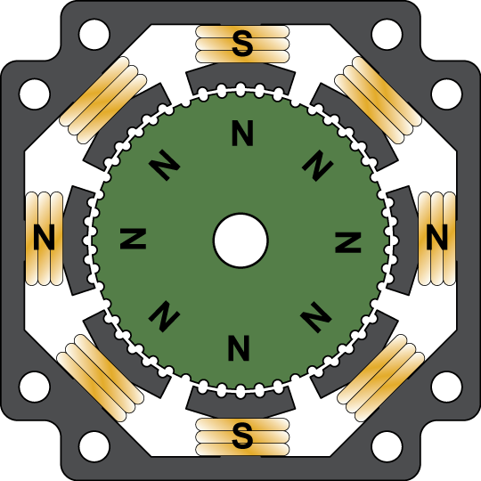 Though it's long been rumored that best step motors are driven by tiny hamsters on wheels contained inside, I can assure you that this is not only untrue, but also promulgated by unscrupulous pneumatic actuator salesmen. So how does a step motor work? In reality, step motors operate by electromagnetism. Specifically, a permanent magnet rotor such as the one shown below is attracted to electromagnets that reside in the stator. Observe that the rotor teeth on the front of the rotor are offset from those on the back. Between the two rotor halves is a strong permanent magnet that ensures all the teeth on the front of the rotor are magnetic north while those on the back are south poles. Remember this; you'll be tested later. When electromagnetic stator coils are connected to a suitable step motor driver, the motor's position, velocity and acceleration can be precisely controlled without any need for feedback. Such simplicity is the reason step motors are a hallmark of the automation industry. If the driver energizes phase A such that two coils are magnetic north and the other two are south, while phase B is off, the rotor aligns as shown below. Notice that the rotor teeth align to the stator teeth of the top and bottom coils. On the back side of the motor, the rotor teeth are offset, and align to the south stator teeth which are currently being repelled on the front of the motor. We can force the rotor to the next position by turning off the current to phase A and applying current to phase B as we see below. To proceed to the next full step position, we turn off phase B and energize the coils of phase A oppositely, so that the top and bottom stator teeth are south and the side teeth are north. To get to the final position, we turn off phase A and energize phase B in reverse. If you command the driver to move the motor including (0.9 deg stepper motor and 1.8 deg stepper motor )at a constant speed, this is what you get. |
 RSS Feed
